For companies dealing with explosive atmospheres, it is essential to have the right safety measures in place. Intrinsically safe (Ex i) equipment is a common method of protection, but often has limited functionality. In this guest blog, explosion safety expert Arnold de Rouw, founder of X-TraCo, explains how hybrid combinations of Ex i with other protection methods such as Ex d (flameproof enclosures) and Ex e (increased safety) enable practical and advanced solutions.
By cleverly applying these combinations, it is possible to have more intelligent and complex electronics and control systems in hazardous areas. This offers major advantages such as more precise process control and greater flexibility, while ensuring that the most stringent safety requirements remain guaranteed. In this blog, De Rouw describes the technical concept, the practical application of a hybrid solution and the important design and installation considerations.
Hybrid Combinations of Protection Modes
The concept of hybrid combinations of Ex i with Ex d and Ex e can be clarified by a practical example. In this hybrid approach, intrinsically safe barriers play a crucial role. These barriers, designated as associated electrical equipment, form the link between the safe and hazardous area. The barriers can be recognized by the text brackets in the marking, for example, [Ex ia Ga] IIC. The brackets indicate that the barrier must be placed outside the hazardous zone, often in an Ex d enclosure.
By connecting the Ex i equipment via such a barrier in an Ex d/Ex e combination, the robustness and functionality can be greatly increased compared to Ex i alone. The practical implementation of such a hybrid solution is explained with an example.
Case Study: Hybrid Solution Ex i Combined with Ex d and Ex e

The image above shows a common practice solution for a hybrid combination of Ex i, Ex d and Ex e. The system consists of:
- An Ex d flameproof enclosure
- An Ex e raised safety enclosure that acts as a junction box
- Ex i equipment such as sensors, transmitters, solenoids, et cetera.
In the Ex d enclosure are all components are mounted that must be outside the hazardous area, such as the Ex i barrier (associated electrical equipment), indicated by [Ex i]. Of course, other non-Ex i components can also be placed in this enclosure.
The Hybrid Combination is Cheaper and Easily Maintainable
This hybrid solution with Ex i, Ex d and Ex e offers some important advantages:
- Cheaper Ex e glands (for increased safety) can be used instead of the more expensive Ex d glands for flameproof enclosure.
- Installation does not require opening the Ex d enclosure, which simplifies the installation process.
- If the system consists only of intrinsically safe cabling (Ex i), live maintenance is permitted. The installation then does not have to be stopped for maintenance work.
Because of these advantages, a hybrid solution offers not only more functionality, but also practical and cost-saving benefits during installation and maintenance compared to Ex d or Ex i only.
Separating Ex i and Non-Ex i
An important point of attention is that the separation between the intrinsically safe (Ex i) part and the non-intrinsically safe components must comply with the EN 60079-14 standard. Practically, this separation can be achieved by using blue cable trays for the Ex i part and gray ones for the non-Ex i part. Galvanic separations, often fed with a 24VDC external voltage, belong to the non-Ex i part.
The cabling is fed through line bushings to the Ex e junction box enclosure. In this Ex e housing the connection terminals are placed. A clear separation between Ex i and non-Ex i parts must also be present here. The distance between the terminal rows must be at least 50 mm. This can be done by either maintaining this 50 mm clearance or by placing a partition. The latter option is recommended as it takes up less space. Any subsequent expansion will thus maintain the 50 mm separation.
Mounting Ex e and Ex d
When mounting the Ex e junction box housing to the Ex d housing, the minimum outlet distance prescribed for the various gas groups must be taken into account:
- Gas group IIA: minimum 10 mm discharge distance
- Gas group IIB: at least 30 mm exit distance
- Gas group IIC: at least 40 mm discharge distance
In the example shown in Figure 1, the height of the Ex e housing is deliberately kept lower than the outlet of the Ex d housing. In this case, therefore, the outlet distance “d” does not have to be taken into account, as it is already wide enough.
Meeting Ex i Standards
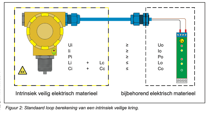
The combination of Ex i, Ex d and Ex e meets the set requirements for a hybrid solution. But in addition, the specific requirements set forth in the Ex i standard must also be met, namely the verification of intrinsic safety, also called the “loop calculation.” Below is the basic method of how this loop calculation for intrinsic safety is performed.
Standard Ex i Loop

A standard intrinsically safe circuit is drawn in Figure 2. Such an Ex i circuit consists of 3 main components that make up the intrinsically safe circuit:
- Intrinsically safe electrical equipment: This is the field equipment such as sensors and pressure transmitters that are allowed to be in the hazardous area. This equipment is marked as Ex ia Ga IIC T5 (note: without text brackets).
- Associated electrical equipment: usually a (zener) barrier, marked as [Ex ia Ga] IIC (with text brackets to indicate that this must be placed outside the hazardous area, e.g. in the Ex d enclosure). The temperature class is missing here.
- Connecting cable: A blue cable or a cable marked “intrinsically safe circuit”.
Because the associated electrical equipment is outside the hazardous area, the temperature class is missing from the marking here. The temperature class in the marking.
Connection of Ex i equipment
The intrinsically safe electrical equipment is connected to the associated electrical equipment via a connecting cable. This connecting cable is blue in color or is marked “intrinsically safe circuit”.
For verification of intrinsic safety, the cable capacitance and inductance must be known. If these data are not available for the cable, then in accordance with the standard it is possible to assume 200 nF/km for the cable capacitance and 1 mH/km for the cable inductance. These values are in accordance with standard EN 60079-11.
Loop Calculation
The loop calculation in its simplest form is shown in Figure 2. The first check performed involves voltage, current and power.
Voltage, Current and Power Check.
The values Ui, Ii and Pi (voltage, current and power) of the intrinsically safe electrical equipment must be greater than or equal to the values Uo, Io and Po of the associated electrical equipment. All these data can always be found in the corresponding Ex certificates.
Inductance and Capacitance
Cable capacitance and inductance have already been mentioned above. These two parameters must also meet certain requirements. Note that the cable parameters are also included in this comparison.
To meet the conditions of intrinsic safety, the maximum specified inductance Lo and capacitance Co must not be exceeded. This means that the summed inductance Li and capacitance Ci of the intrinsically safe equipment and the cable inductance Lc and capacitance Cc, must never exceed Lo and Co of the (zener) barrier.
If all conditions stated in Figure 2 are met, then the circuit meets intrinsic safety.
Additional Requirements
Note that the basic requirements for a hybrid solution are now met. In practice, some skills are necessary in addition to the aforementioned requirements:
- Basic ATEX training
- Understanding of intrinsic safety
- Being able to read and correctly interpret certificates
- Applying the 1% regulation
- Checking functional operation of the system
Hybrid solutions training
If you wish to receive more information after this explanation of a hybrid Ex i/Ex d/Ex e solution, Cobic and X-TraCo can provide training sessions that provide the necessary skills as listed above.


